
Wi-Fi at home. 4G on the highway. 5G downtown. Three different names, but under the hood they all run on the same workhorse: OFDM — Orthogonal Frequency Division Multiplexing. It’s the backbone of today’s wireless systems, and very likely 6G too.
In my new video lecture, I build an OFDM transmitter from scratch — casually, step by step, so even complete beginners can follow. This post is the written tour of that journey. Grab a coffee, and let’s build a transmitter together.
How does a radio wave carry information at all?
Everything in wireless starts with an electromagnetic wave. Think of it as a hum flying through the air. On its own, a hum says nothing. So how do we make it talk?
We twist two knobs. One knob controls the wave’s strength — its amplitude. The other controls its timing — its phase. The transmitter sets the knobs, the wave flies, and the receiver reads the knob positions and turns them back into information. That’s wireless communication in one sentence.

Meet the villain: multipath
Shout “HELLO!” into a canyon. You hear your own voice come back — once, twice, each copy a little later and a little weaker. Radio waves do exactly this. They bounce off buildings, hills, and walls, and the receiver catches several delayed, weaker copies all added together. Engineers call this multipath propagation.

Let’s give everything between the transmitter and the receiver a name: the channel. Now here’s a hopeful thought. If the channel simply scaled the signal — one clean multiplication — the receiver could measure that multiplier and just undo it: divide the received signal by the scaling factor, and the message is recovered.

The spiral trick: why engineers love complex numbers
Instead of drawing the wave as a flat wiggle, write it as ej2πft and draw it in 3D. It becomes a spiral — a spring turning forward through time. Look at the spring from the front and you see the cos (the real part). Look from the top and you see the sine (the imaginary part). Same object, two shadows.
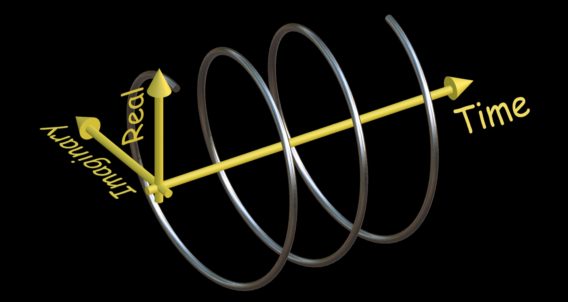

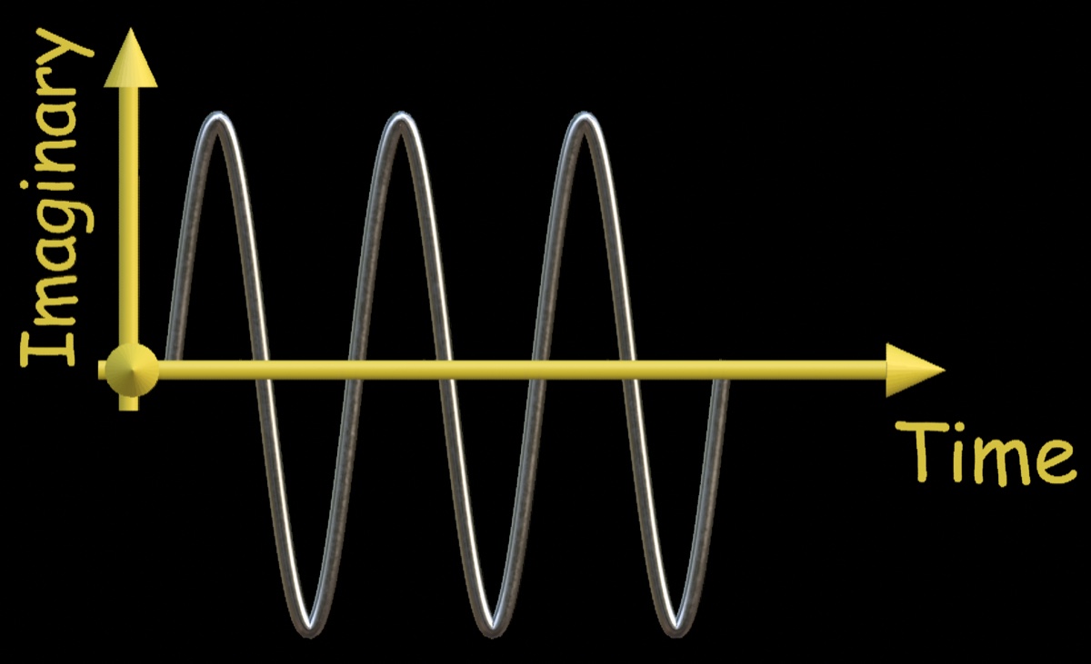
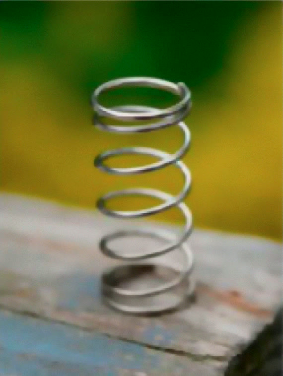
Sound abstract? It shouldn’t. You’ve been walking past this exact shape your whole life:

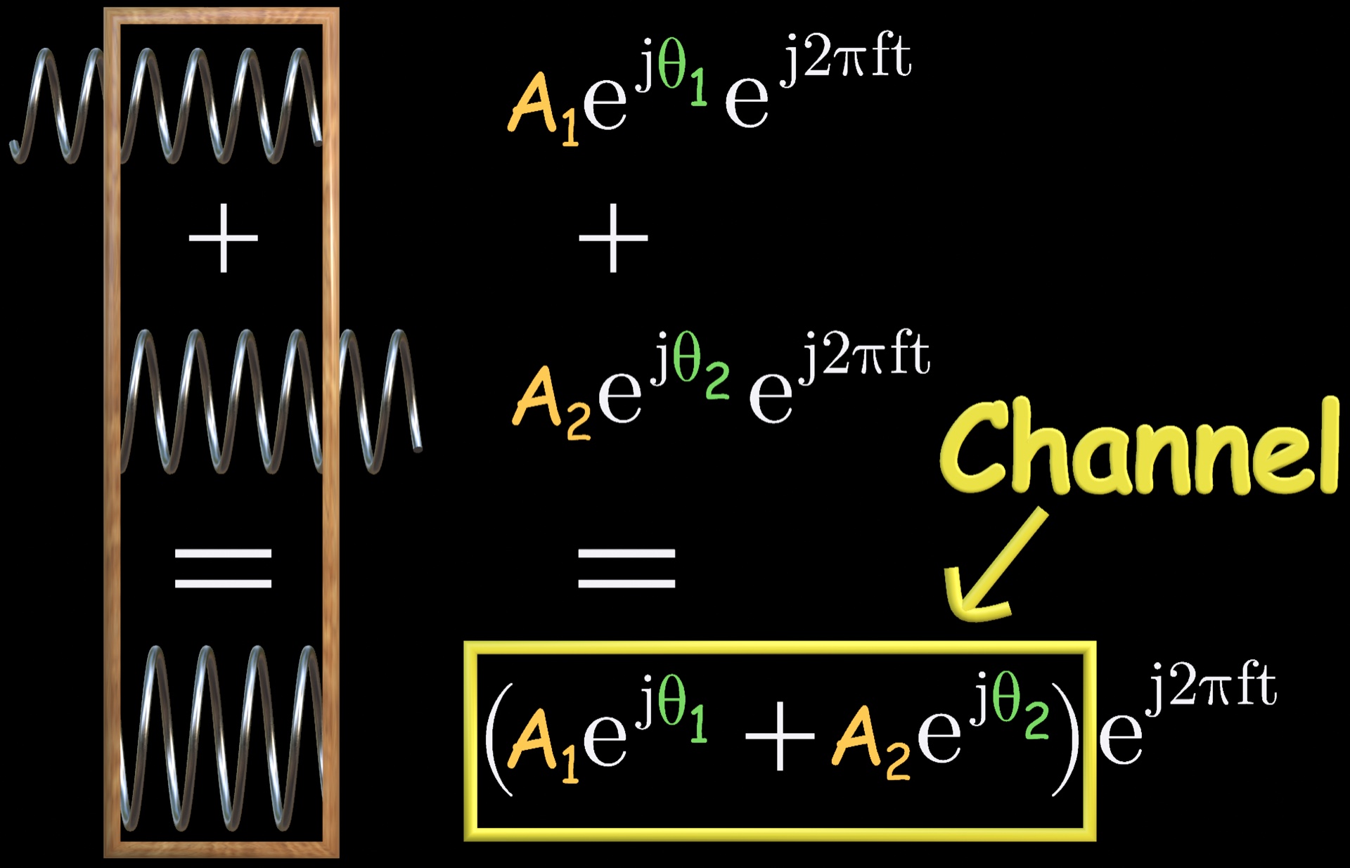
Now delay that spring. Slide it back in time and watch it through a fixed picture frame. What do you see inside the frame? The same spring — just rotated. In the complex world, a delay is nothing but a rotation — a delay is simply a phase shift. In math clothes: rotating the spiral by an angle θ is the same as multiplying it by ejθ. And scaling plus rotating is exactly what multiplying by one complex number does!
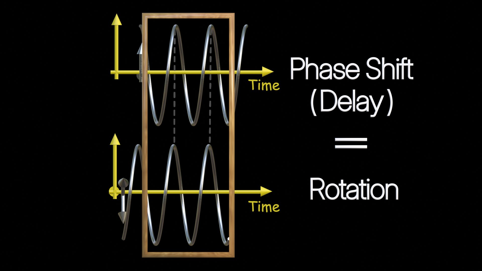
So when the canyon adds many delayed, scaled copies of our spiral together, the result is — drum roll — still the same spiral, with a new amplitude and a new phase. In other words, the spiral shape is a survivor: scale it, rotate it, add any number of delayed copies — what comes out is always the same spiral shape (engineers would say it is invariant). The whole villainous channel collapses into one complex multiplier. The receiver estimates it with a pilot and undoes it. Villain tamed.
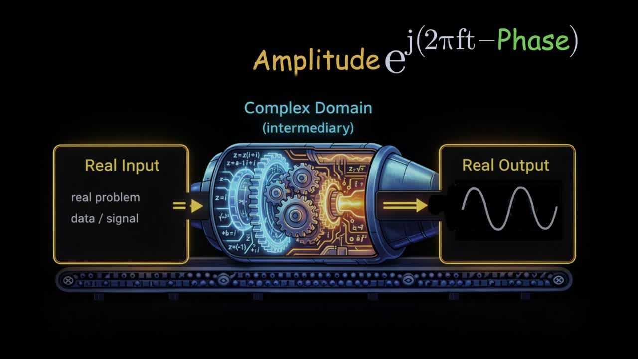
That’s why I like to call the complex domain a hidden engine. Real signal goes in, the math becomes wonderfully easy inside this complex engine, real signal comes out. The airwaves never know we used imaginary numbers.
From bits to waves: QAM in one minute
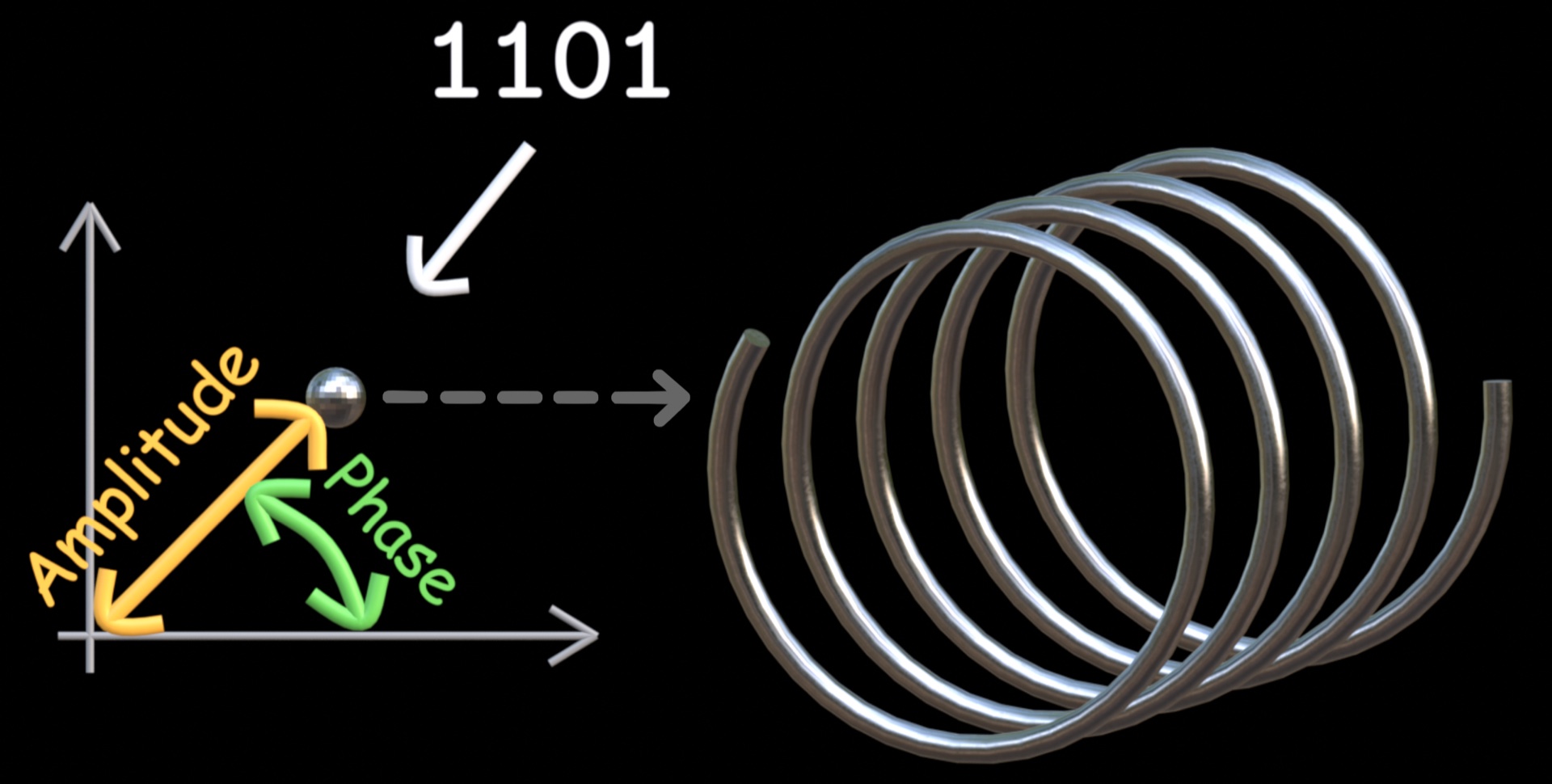
Freeze the spiral, and the whole thing can be represented as a single point on a 2D plane: the point’s distance from the origin is the amplitude, and its angle is the phase. Now the fun part — we place information on the wave by choosing points: different bit groups correspond to different points — that is, different spirals, each with its own amplitude and phase. Group your bits, say four at a time, and let each group pick one specific point. Bits become geometry. This mapping is called QAM modulation (I have a whole post and video on it, so I’ll stay brief here).
One last ingredient. Every transmitter carries a local oscillator — a tiny circuit that hums out a steady, very fast wave, whose job is to lift our signal up to radio frequency. The transmitter chain so far: group the bits → map them to QAM symbols → multiply by the local oscillator’s wave → transmit the real part. Done. That’s a working single-carrier transmitter.

The echo strikes back: cyclic prefix
One problem left. We send symbols back-to-back, and the canyon’s late echoes of symbol 1 smear into symbol 2. That’s Inter-Symbol Interference (ISI). We could leave a silent gap between symbols — but silence is wasted airtime.
OFDM does something smarter. It copies a short piece from the end of each symbol and pastes it at the start. This copy is the cyclic prefix. The receiver simply ignores it, so the previous symbol’s echoes crash harmlessly into the prefix instead of the useful data. Think of it as a crumple zone on a car — sacrificial by design.

Why stop at one wave? Subcarriers and the “O” in OFDM
Sending one symbol at a time is like shipping one parcel per truck. To go faster, OFDM sends thousands of subcarriers in parallel, each carrying its own QAM symbol.

In 4G, the spacing is 15 kHz, so the useful symbol lasts about 66 microseconds — and hundreds of subcarriers sit side by side to fill wide bandwidths: a 10 MHz 4G channel, for example, packs 600 of them. This same trick powers far more than cellular: Wi-Fi has used OFDM since 802.11a in 1999, and digital TV broadcasting (DVB-T) rides on it too.

Jargon translator: the time–frequency grid
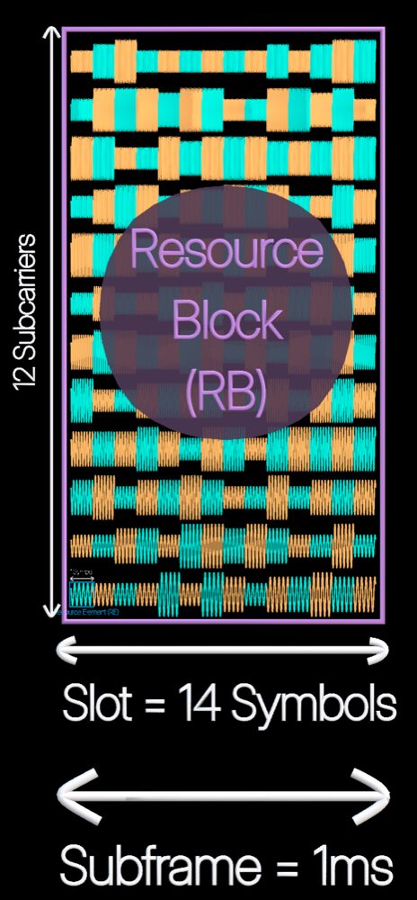
Now you can decode the vocabulary you’ll hear everywhere in wireless. Picture a grid: frequency runs vertically (subcarriers), time runs horizontally (symbols).
- Resource Element (RE) — one subcarrier over one symbol. It carries exactly one QAM symbol. The smallest pixel of the picture.
- Slot — 14 symbols in a row.
- Resource Block (RB) — 12 subcarriers over one slot. This is the convenient chunk the network assigns to your phone.
- Subframe — always 1 ms of time. Frame — always 10 ms.
Here’s the neat coincidence in 4G: one symbol (cyclic prefix + 66 µs useful part) times 14 comes out to almost exactly 1 ms. So in 4G, one subframe holds exactly one slot. Keep that in mind — it’s about to break, beautifully, in 5G.
Finally: what is numerology?
5G asked a bold question: why should the subcarrier spacing be locked at 15 kHz forever? So it unlocked the dial. 5G supports spacings of 15, 30, 60, 120, even 240 kHz — each option is called a numerology (µ), and the spacing is simply 15 kHz × 2µ, as defined in the 3GPP standard TS 38.211.
Remember the rule: symbol duration is the inverse of the subcarrier spacing. Double the spacing, and the symbol duration halves — and since a slot is just 14 symbols in a row, the slot duration halves right along with it. But the subframe is always 1 ms. So more slots squeeze into each subframe:
| µ | Spacing | Slot length | Slots per subframe |
|---|---|---|---|
| 0 | 15 kHz | 1 ms | 1 |
| 1 | 30 kHz | 0.5 ms | 2 |
| 2 | 60 kHz | 0.25 ms | 4 |
| 3 | 120 kHz | 0.125 ms | 8 |
| 4 | 240 kHz | 0.0625 ms | 16 |
Why bother? Shorter slots mean the network gets more scheduling chances per millisecond — great for low-latency applications like gaming or industrial control. And up in the millimeter-wave bands, a wider subcarrier spacing also keeps the subcarriers robust against frequency wobble. There is a tradeoff, though: shorter symbols come with a proportionally shorter cyclic prefix — a smaller crumple zone — so they can absorb only short echoes. That’s why the fast numerologies (higher µ) typically serve short distances, while the slow ones (lower µ) stretch to wide-area coverage. Numerology is 5G’s tempo dial: slow and steady for wide coverage, fast and snappy when milliseconds matter.
The whole transmitter in one breath
- Group information bits → map them to QAM symbols
- Place symbols on orthogonal subcarriers → add the cyclic prefix
- Arrange everything on the time–frequency grid — that’s the baseband
- Multiply by the carrier, transmit the real part — that’s the passband
- The receiver just runs the movie backwards
And that’s it — the signal is on its way! I skipped plenty of implementation details for clarity — for those, my What is OFDM? post and its video are the place to go. Let me know your thoughts in the comments. Until next time — happy learning!
Leave a Reply